-
-
CL Solutions
Cathodoluminescence solutions that reveal fundamental properties of matter
-
Cryo Solutions
Integrated and automated solutions to u nlock the power of cryo - ET workflow -
FAST IMAGING
Fast EM solutions for reliable and high throughput electron microscopy
-
CLEM Solutions
Integrated correlative microscopy solutions that combine the power of fluorescence and electron microscopy
-
CL Solutions
- Contact
- All resources
-
CL Solutions
Cathodoluminescence solutions that reveal fundamental properties of matter
-
Cryo Solutions
Integrated and automated solutions to u nlock the power of cryo - ET workflow -
FAST IMAGING
Fast EM solutions for reliable and high throughput electron microscopy
-
CLEM Solutions
Integrated correlative microscopy solutions that combine the power of fluorescence and electron microscopy
CL Solutions
Cathodoluminescence imaging: frequently asked questions
Answering the most common questions about cathodoluminescence imaging and our CL solutions.
Cathodoluminescence imaging
-
What are the benefits of cathodoluminescence(CL) imaging?
CL can be excited at high spatial resolution by a focussed electron beam, such as in a Scanning Electron Microscope, making CL imaging a high resolution optical imaging technique. This makes it possible to investigate samples at nanoscale resolution, which is not possible for conventional optical techniques due to the diffraction limit of light. Correlative CL imaging is often performed with techniques such as BSE, EDX or EBSD imaging to obtain complementary information about the sample.
-
What is the difference between CL and other SEM-based imaging techniques?
Secondary electrons (SE) detection is a detection of low-energy electrons, with which it is possible to collect secondary electrons only from the top few nanometers of a material. This technique is sensitive to surface topography and also shows (minor) material contrast. Backscattered electrons (BSE) detection is primarily sensitive to density and atomic number and as such can be used to obtain material contrast. With electron backscattered diffraction (EBSD) you can look at the crystal structure and crystal orientation. Energy dispersive X-ray spectroscopy (EDS) is used to get quantitative material composition by looking at core transitions in the material. CL contrast contains information about the material composition, as well as about the band gap, defects, trace elements, crystal defects, and optical resonances.
-
In which fields is cathodoluminescence imaging currently being used?
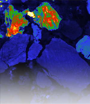
CL imaging is popular in a wide range of fields from geology and earth and marine sciences to semiconductors, solar cells, photonics, plasmonics, and life sciences. The different CL imaging modes allow the study of different properties of light, such as the emission intensity, angular distribution, spectral composition and polarisation. These in turn help to understand different sample properties. The dynamics of light emission can also be studied.
-
What are the most commonly used CL imaging modes?
The most commonly used CL imaging modes are panchromatic intensity mapping, RGB intensity mapping and spectroscopy. Advanced imaging modes such as angle-resolved imaging, polarimetry, energy-momentum imaging and time-resolved imaging can provide further insight into sample properties and are often used in fields like plasmonics and nanophotonics. If you would like to know more about each imaging mode, please visit the CL technique page.
-
What is the difference between cathodoluminescence and photoluminescence?
CL, in broad terms, is the process of light emission from a material as a result of excitation by electrons. It therefore provide a signature of the electronic excitation processes. PL is the process of light emission as a result of excitation by photons. Since electrons are massive and carry more momentum, the selection rules for CL emission are different from those for PL. The light sources, often lasers, used for PL excitation have a narrow energy range and therefore probe specific transitions. Excitation by electrons, on the other hand, is broad band, allowing inspection from the deep UV to the IR. Moreover, due to the high energy of the electrons, multiple excitation paths are available, resulting in different relaxation pathways with corresponding CL signatures. Materials can also show both CL and PL.

-
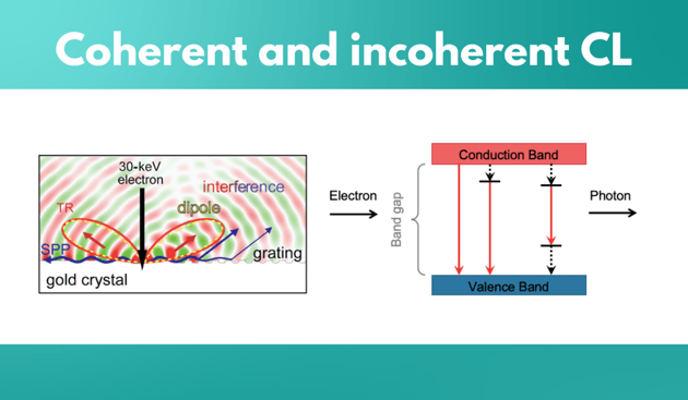
What is the difference between coherent and incoherent CL?
Incoherent cathodoluminescence emission occurs when the material is excited with an electron beam, where the primary electrons decelerate and deposit energy into the material.
An important property of incoherent CL is that there is no fixed phase relation between a photon that is emitted and incoming excitation electron. This CL type is spontaneous, it’s not phase correlated with the excitation, and it is unpolarised if the medium is homogeneous. Coherent cathodoluminescence is generated whenever there is a difference in refractive index in the propagating path of the electron. If material is in a vacuum, the interface between the material and vacuum would allow the generation of coherent CL. For example, if a high energy beam is exciting a gold crystal, it polarises the material at the interface, and because of this, an oscillating charge is created. Unlike in incoherent CL, the emitted photon has a fixed phase relation with incoming electron. In addition, the emitted light is always polarised. Coherent CL is always present but can be obscured by incoherent CL as it is a low probability event. For example, it is present in materials such as direct bandgap semiconductors, phosphors, and ceramics, but it is obscured by the higher probability of incoherent CL emission. In metals and indirect bandgap semiconductors, on the other hand, incoherent CL is suppressed by non-radiative channels, because of which coherent CL emission dominates.
Sample preparation
-
How should the sample be prepared for cathodoluminescence imaging?
To perform cathodoluminescence imaging, the sample needs to be conducting, or coated with a conducting layer, in order to prevent charging under the electron beam. The sample should ideally be flat. Both these requirements are also necessary for SEM imaging, so there is often no additional sample preparation needed for CL imaging. It is also possible to image samples in powder form, by ensuring they are glued to the sample holder.
Learn more about sample preparation from our blog -
Is it possible to perform CL imaging on a non-conducting sample without coating it?
Sometimes coating the sample is undesirable as it is needed in pristine form for other measurements, such as EDX. It is possible to perform CL imaging in the presence of a gas that is let into the chamber to counter charging. This requires an environmental or high pressure SEM.
-
Is CL imaging a non-destructive technique?
CL imaging requires the sample to be exposed to the electron beam. Whether the sample is in any way modified by electrons depends on several factors like the composition of the sample itself, the electron dose, and the electron energy. Some samples such as semiconductors are very stable under electron exposure. It is important to test the behaviour of the sample at the desired imaging parameters and it is sometimes necessary to select the parameters based on how the sample behaves. If the sample charges or shows heating effects, for example, it may be necessary to use a lower current or beam energy or both. Even if the sample is stable in a vacuum and is conducting, the interaction of the electron beam with the sample may cause damage because of heating, bond breaking or other effects. The SEM contrast can be used to monitor changes to the shape/form of the sample, and often the spectral signature can be used to monitor changes at the crystal or molecular level.
-
How should I prepare my geological samples?
Two techniques are used to prepare geological materials - thin-sectioning (20 to 30 microns) and resin embedding.
Learn more about using CL for geology -
What are the restrictions on sample dimensions for CL imaging?
A wide range of sample sizes is allowed. Large samples can be imaged using automated tiling and stitching, performed by scanning the SEM stage. The sample thickness in itself is not limiting, however it is important to keep in mind that CL is generated in the interaction volume of the electrons in the material. Therefore, having a thick sample can sometimes lead to higher background signal.
Cathodoluminescence detectors
-
What are the different cathodoluminescence detectors available and what are the differences between them?
There are three CL detectors: JOLT, SPARC Compact and SPARC Spectral. The JOLT is an entry-level detector that is very easy to use and contains no moving parts. It is used for panchromatic and RGB intensity mapping. The SPARC Compact and Spectral systems both use a polished parabolic mirror and therefore provide more efficient light collection, which is particularly beneficial for low emission and beam-sensitive samples. The SPARC Compact is used for panchromatic and RGB intensity mapping, whereas the SPARC Spectral can perform spectroscopy as well. Various advanced imaging modes such as angle-resolved imaging, polarimetry, energy-momentum imaging and time-resolved imaging are possible with the SPARC Spectral. All the CL detectors are retro-fits, compatible with SEM’s from most manufacturers.
Learn more about our high-end CL detector SPARC Spectral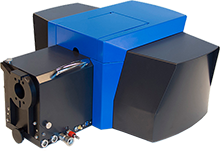
-
How does the JOLT perform RGB imaging?
The JOLT is mounted at a fixed height above the sample and collects all the light that reaches it. No alignment is required. Although less sensitive than the SPARC systems, it is suitable for a variety of applications. The RGB JOLT has filters which allow the acquisition of different channels, and the readout is sequential.
Learn more about our entry-level CL detector JOLT
-
How is CL imaging performed on the SPARC?
The sample is mounted in the SEM in the standard manner and excited by the focussed electron beam. The light generated is collected by a polished parabolic mirror that is mounted above the sample, and sent to the detector, such as a PMT, spectrograph, or fiber outcoupled. In order to ensure efficient light collection, the mirror must be aligned such that the sample is at its focal position. This alignment is a critical step in CL imaging and is performed in a highly accurate and reproducible manner using a piezo controlled micropositioning system. The data acquisition is performed using the open-source Odemis control and acquisition software.
Download the specifications sheet of SPARC Spectral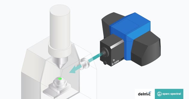
-
What optics and detectors are available on the SPARC Spectral system?
The SPARC Spectral is a very modular system. The optics and detectors are configured to suit the sample/research problem. This means selecting the optimal optics modules, cameras and diffraction gratings for the wavelength range needed (UV, VIS-NIR, IR). It is possible to have several modules and switch between them.
Configure your ideal SPARC Spectral system

Didn't find an answer?
Fill in the form with your question, and our experts will get back to you soon!
