Cryogenic electron microscopy (Cryo-EM) fundamentals

Cryo electron microscopy (cryo EM) is a Nobel prize-winning imaging technique that allows scientists to observe biomolecules at sub-nanometer resolution.

chapter 1

What is cryogenic electron microscopy (cryo EM)?

Transmission Electron Microscopes (TEMs) transmit a beam of electrons through a sample to create an image. While the electrons pass through the sample, some will be scattered by heavier atoms in the sample creating a projection image. Imaging of biological material with EM requires protection of the sample from the high vacuum conditions and the intense beam of electrons. The electrons transfer a high amount of energy into the sample that destroys the structure while the vacuum causes the water that surrounds the molecules to evaporate. A way to protect the sample from these extreme conditions is cryogenics. By rapidly freezing, the sample is vitrified and adopts a glass-like state, without formation of ice crystals. In this state the sample deteriorates much slower, allowing the study of biological material using TEM.

https://request.delmic.com/hubfs/METEOR_GuidedCryoLamellae_BlogImage-2.png

Subscribe to the cryo-EM newsletter

Would you like to receive monthly updates on the developments and applications in the cryo-EM field? Fill in the form below!

chapter 2

What is cryogenic electron tomography?

Cryogenic electron tomography (cryo-ET) is an imaging technique used to obtain high resolution 3D reconstructions of biomolecules.

In cryo-ET a vitrified sample is imaged in a TEM as it is tilted from approximately -60⁰ to +60⁰. This results in a series of 2D images that can be combined to reconstruct a 3D image, a so-called tomogram. This technique is powerful enough to resolve 3D structures of intracellular organelles and protein complexes in near-native state in their cellular environment. Resolving structures in their cellular context is a groundbreaking advancement for structural and cellular biology. The location, as well as the structure of a biomolecule, is crucial to the understanding of its cellular function.

https://request.delmic.com/hubfs/Website%20Content%20Offers/Brochures%20and%20Spec%20Sheets/Thumbnail%20Cryo/2022_METEOR_Brochure_ResourceLib_Thumbnail.png
Brochure

Learn about METEOR, the top-down cryo-FLM

Read now
chapter 3

In what research areas is cryo-ET applied?

Cryo-ET was originally mainly used in structural biology, but due to the recent technological advances it has become a powerful tool that is applied in a wide range of research areas, such as microbiology, neurobiology, immunology, cell biology, developmental biology and molecular biology.

Researchers in microbiology use cryo-ET to visualize viral infections in bacteria. By employing cryo-ET researchers could for example reconstruct the structure of viruses in different stages of infection. In another study they used cryo-ET to show that viruses create a nucleus-like structure in bacteria to protect themselves from the hosts’ defence mechanisms’  [1], [2].

Cryo-ET is used in neurobiology to visualize protein aggregation that leads to neurodegenerative disorders. Traditional methods for sample preparation of neuronal cells do not allow high resolution imaging, but by employing cryo-ET researchers were able to visualize aggregates associated with Huntington’s disease and lateral sclerosis [3], [4].

In immunology researchers employ cryo-ET to study the structure of HIV-1 particles bound to HeLa cells, revealing their interaction [5].

In cell biology, cryo-ET has been used to shed light on the connections between different intracellular membrane systems by membrane contact sites. The high resolution 3D reconstructions arising from cryo-ET allow the study of the molecules involved in these rare contacts between different organelles [6], [7].

To date, cryo-ET is mainly performed using cultured cells or single-celled organisms. To use cryo-ET for developmental biology studies in multicellular organisms, new protocols have been developed that allow classical model organisms, such as C. Elegans and D. Melanogaster [8], [9].

Recent research in the field of molecular biology uncovered important structural details of purified Cas9 using cryo-EM [10]. Taking this research further by using cryo-ET to catch CRISPR-Cas9 in action in situ will assist greatly in optimizing this famous gene-editing system.

Watch the discussion about the article: Ribosome-associated vesicles: A dynamic subcompartment of the endoplasmic reticulum in secretory cells.


https://request.delmic.com/hubfs/Website/News/Journal%20Club%20Series%20Overview_Banner_Blogpost.png
cryo-et journal club webinar series

Join us to discuss the recently published leading papers about cryo-ET

Sign up
chapter 4

How are samples prepared for cryo-ET?

Samples are vitrified by plunge freezing or high pressure freezing

To vitrify a sample several techniques are available, the most widely used are plunge freezing and high pressure freezing. The choice of the technique mainly depends on the size of the sample. For samples thinner than 10 µm plunge freezing can be used. In this method the grid is rapidly plunged in a cryogen (e.g. liquid ethane) cooled by liquid nitrogen. For samples thicker than 10 µm, sufficiently high cooling rates cannot be obtained by plunge freezing. A slow freezing rate causes formation of ice crystals, which damages the sample. For this reason, thicker samples are often frozen using high-pressure freezing, which can be used for samples with a thickness of up to 200 µm. Here, the sample is frozen under high pressure (2100 bar), which allows adequate freezing rates for vitrification.

Samples are thinned by cryo-FIB milling or by cryo-ultramicrotomy

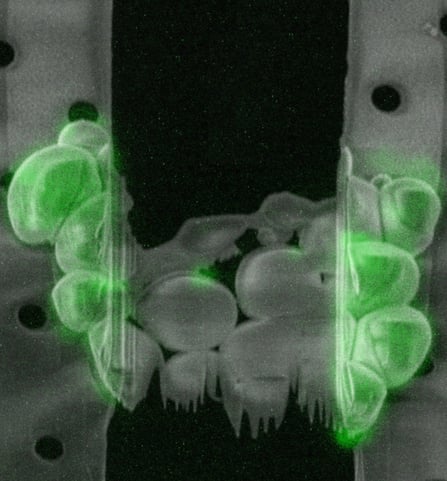
The maximum resolution of a TEM scales down with the increased thickness of the sample. Therefore, to obtain a high resolution tomogram samples should ideally be between 100 and 300 nm thick. A vitrified sample can be sectioned using cryo-ultramicrotomy: cutting the sample with diamond knife under cryogenic conditions. This technique, however, has a number drawbacks, the sections tend to have physical defects, get compressed and wrinkled, making them difficult to image. The most successful technique to prepare a thin section within the sample, a so-called lamella, is milling using a focussed ion beam (FIB). With this technique, a focussed beam of gallium ions at high current is used to sputter away material around the region of interest (ROI) to create a lamella. This process is performed in a scanning electron microscope (SEM) fitted with a FIB (FIB/SEM) that is equipped with a cryo-stage to keep the sample under cryogenic temperatures.

Regions of interest are identified by cryogenic fluorescence light microscopy

Identifying the ROI to mill in the right location is a crucial step, since being off target for this process could result in milling away your structure of interest. To overcome this, cryogenic fluorescence light microscopy (cryo-FLM) is often used. In this technique biomolecules of interest are fluorescently labelled and the sample is first imaged with cryo-FLM to identify the ROI. The FIB is then used to create a thin lamella in the sample exactly at the ROI and the sample is transferred to the cryo-TEM for high resolution imaging. This method has become the gold standard for cryo-ET since it produces high resolution EM data that is superbly correlated with FLM while the cryogenic conditions keep samples at a near-native state. However, this method is very laborious and error prone since the sample needs to be transferred between three different microscopes.

https://request.delmic.com/hubfs/Website/Webinars%20Thumbnails/2021%20Update%20Webinar%20Thumbnails/2021_METEOR%20Demo_Webinars_ResourceLib_Thumbnail.jpg
Online demo

Watch the demo of METEOR, the first integrated cryo-CLEM system

Watch now
chapter 5

How do I optimize the cryo-ET workflow?

Optimization by integration - Integrating a fluorescence light microscope into the FIB/SEM

As was discussed in the previous sections, the optimal method to process a sample for cryo-ET is also the most laborious and includes three different microscopes. The fragile sample needs to be transferred from the cryo-FLM to the cryo-FIB/SEM and then to the cryo-TEM, all while maintaining a temperature below -160°C. To complicate things further, the sample is often transferred back to the cryo-FLM after FIB milling to confirm that the ROI is still present in the lamella. These transfer steps make the workflow an exceedingly challenging task that translates in a low sample preparation success rate of approximately 20%. At Delmic we have designed several products that integrate fluorescence microscopy into a cryo-FIB/SEM system. These designs abolish the need for a separate cryo-FLM system and most importantly, reduce sample handling. Using an integrated FLM in the FIB/SEM means that ROI identification by FLM, SEM imaging, FIB milling and ROI confirmation by FLM can all be done in the same system without the need to handle the sample, thus increasing the success rate of the cryo-ET workflow considerably.


The current cryo-ET workflow is a complicated and long procedure that requires a highly experienced operator. Integrating FLM imaging into the FIB/SEM increases the success rate significantly, but more can be done to optimize the entire workflow.

2022_Cryo-ET_TEM-Website

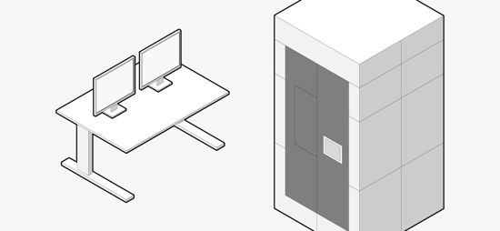
Many cryo-TEMs are capable of processing multiple samples using an autoloader system, but in the rest of the cryo-ET workflow, sample preparation in batch is not possible. To tackle this issue, we introduce an automated sample transfer system for the FIB/SEM. This system uses cassettes that hold up to 12 grids and is compatible with autoloader systems on most existing cryo-TEM systems. The automated transfer system works under vacuum and cools the samples without submerging them in liquid nitrogen, which reduces contamination risk. This results in a workflow that abolishes the need for manual handling of grids after sample vitrification and loading into the cassette. Reducing the handling steps and necessary transfers translates into a major leap forward in efficiency and success rate.


Optimization by sample processing automation – Automatic FIB milling and ROI validation

A third optimization point in the workflow is the milling of the lamellae. This process is usually performed by manually selecting a ROI and then designing and milling the lamella. Here, specialized software can assist in automating the milling process. After an overview of a grid is captured in fluorescence mode, ROIs are selected and detailed Z-stacks of the regions are captured in FML mode. In this detailed fluorescence map, the exact location of the point of interest is selected and the lamellae are automatically milled and FLM images are taken afterwards to check whether the lamellae still contain the region of interest. This process can be performed in batch with many grids to have the system perform the milling of the lamellae unassisted overnight, freeing up time on the system.

Together, our solutions reduce the exceedingly challenging cryo-ET sample preparation workflow to a few simple tasks, paving the way to making cryo-ET a routine technique.

https://request.delmic.com/hubfs/Website/Webinars%20Thumbnails/2021%20Update%20Webinar%20Thumbnails/2021_Minimizing%20Sample%20Contamination_Webinars_ResourceLib_Thumbnail.jpg
Webinar

Minimizing sample contamination with CERES

Watch now
chapter 6

What is the future of cryo-ET?

Technological Advances will make cryo-ET a routine technique

Obtaining a tilt series in a TEM currently takes 20-60 minutes which slows down the cryo-ET workflow considerably. Fortunately, next-generation direct detectors, hardware for faster data transfer as well as methods for rapid tilt series are currently being developed [11]. Combined, a tilt series could be obtained in only a fraction of the time it currently takes, speeding up the workflow considerably. This development also increases the need for easy and automatic sample preparation methods to optimally make use of the cryo-TEM. Automatic sample preparation combined with high-speed TEM acquisition will result in the possibility to resolve large amounts of biological structures.

As more and more structures become available data processing could be optimized by automatic mapping. A tomogram that contains several biological structures could be automatically screened against a database. Known structures would be fitted to the structures visible in the tomogram, showing which known structures are present. Routinely obtaining biological structures could also result in the rise of quantitative structural biology: doing statistical analysis to gain a deeper understanding of structure-to-structure variations.

Cryo-ET will reveal structural information of many cellular processes and pathways

A major step forward has been made possible by cryo-ET by moving from obtaining structural data in purified samples to getting the same high resolution data in their biological context, or in situ. At the moment, many studies are focusing on large protein complexes that “stand out of the crowd” due to their known size or location, making them relatively easier to identify and image. As the cryo-ET technology develops further, it will become easier to identify increasingly rare cellular structures and events. Obtaining high resolution structural data of rare cellular events will have a great impact on fields such as drug development and cellular immunology, but will also likely reshape our knowledge on many of the textbook signalling pathways and trafficking routes of the cell.

Even though proteins often assemble in stable multiprotein complexes, most protein-protein interactions are transient in nature [12]. These interactions, often accompanied by changes in protein fold or shape, hold crucial information on how and where important processes take place. Capturing the structural detail of such transient interactions in their cellular context seems like an unobtainable feat at the moment, but with the current advancements in cryo-ET technology, it might not be that far away.

Likewise in the field of nucleic acid research, cryo-ET can play a fundamental role unravelling processes such as the post-transcriptional regulation by (non-coding) RNA. The change in secondary structure of RNA can directly translate into a specific function, such as regulation of gene expression, protein interaction or RNA-RNA interaction [13]. Since the first discoveries of non-coding RNA molecules, it has become apparent that RNA molecules regulate a host of complex cellular processes that are tied strongly to their confirmation [14]. Here, cryo-ET could shed further light on the structure-function relation of RNA in its cellular context. Here the challenge lies in the vast amount of content in the cytoplasm and the relatively small size of signalling RNA molecules. For this, increased precision in finding molecules of interest with cryo-FLM and increased signal-to-noise ratio to resolve structures in the crowded cytoplasm are needed.

At Delmic we strongly believe that cryo-ET will revolutionize the field of structural biology and become the method of choice to obtain the 3D structure of a biomolecule. We aim to make cryo-ET more accessible to researchers by providing solutions that simplify the workflow. We do so by consolidating the sample preparation workflow with an automated approach.

https://request.delmic.com/hubfs/Website%20Content%20Offers/Brochures%20and%20Spec%20Sheets/Thumbnail%20Cryo/2021_CERES_Brochure_Thumbnail.png
Brochure

Meet CERES Ice Defence System

Learn more
Cryo-ET

References

[1]           W. Dai et al., “Visualizing virus assembly intermediates inside marine cyanobacteria,” Nature, vol. 502, no. 7473, pp. 707–710, 2013, doi: 10.1038/nature12604.

[2]           V. Chaikeeratisak et al., “Assembly of a nucleus-like structure during viral replication in bacteria,” Science (80-. )., vol. 355, no. 6321, pp. 194–197, Jan. 2017, doi: 10.1126/science.aal2130.

[3]           F. J. B. Bäuerlein et al., “In Situ Architecture and Cellular Interactions of PolyQ Inclusions,” Cell, vol. 171, no. 1, pp. 179-187.e10, Sep. 2017, doi: 10.1016/j.cell.2017.08.009.

[4]           Q. Guo et al., “In Situ Structure of Neuronal C9orf72 Poly-GA Aggregates Reveals Proteasome Recruitment,” Cell, vol. 172, no. 4, pp. 696-705.e12, Feb. 2018, doi: 10.1016/j.cell.2017.12.030.

[5]           J. D. Strauss, J. E. Hammonds, H. Yi, L. Ding, P. Spearman, & E. R. Wright (2016). Three-Dimensional Structural Characterization of HIV-1 Tethered to Human Cells. Journal of Virology90(3), 1507–1521. https://doi.org/10.1128/jvi.01880-15.

[6]           J. Collado and R. Fernández-Busnadiego, “Deciphering the molecular architecture of membrane contact sites by cryo-electron tomography,” Biochimica et Biophysica Acta - Molecular Cell Research, vol. 1864, no. 9. Elsevier B.V., pp. 1507–1512, 01-Sep-2017, doi: 10.1016/j.bbamcr.2017.03.009.

[7]           P. C. Hoffmann, T. A. M. Bharat, M. R. Wozny, J. Boulanger, E. A. Miller, and W. Kukulski, “Tricalbins Contribute to Cellular Lipid Flux and Form Curved ER-PM Contacts that Are Bridged by Rod-Shaped Structures,” Dev. Cell, vol. 51, no. 4, pp. 488-502.e8, Nov. 2019, doi: 10.1016/j.devcel.2019.09.019.

[8]           M. Schaffer et al., “A cryo-FIB lift-out technique enables molecular-resolution cryo-ET within native Caenorhabditis elegans tissue,” Nat. Methods, vol. 16, no. 8, pp. 757–762, 2019, doi: 10.1038/s41592-019-0497-5.

[9]           J. Harapin, M. Börmel, K. T. Sapra, D. Brunner, A. Kaech, and O. Medalia, “Structural analysis of multicellular organisms with cryo-electron tomography,” Nat. Methods, vol. 12, no. 7, pp. 634–636, Jun. 2015, doi: 10.1038/nmeth.3401.

[10]         X. Zhu et al., “Cryo-EM structures reveal coordinated domain motions that govern DNA cleavage by Cas9,” Nat. Struct. Mol. Biol., vol. 26, no. 8, pp. 679–685, Aug. 2019, doi: 10.1038/s41594-019-0258-2.

[11]         G. Chreifi, S. Chen, L. A. Metskas, M. Kaplan, and G. J. Jensen, “Rapid tilt-series acquisition for electron cryotomography,” J. Struct. Biol., vol. 205, no. 2, pp. 163–169, Feb. 2019, doi: 10.1016/j.jsb.2018.12.008.

[12]         J. R. Perkins, I. Diboun, B. H. Dessailly, J. G. Lees, and C. Orengo, “Transient Protein-Protein Interactions: Structural, Functional, and Network Properties,” Structure, vol. 18, no. 10. pp. 1233–1243, 13-Oct-2010, doi: 10.1016/j.str.2010.08.007.

[13]         J. J. Quinn and H. Y. Chang, “Unique features of long non-coding RNA biogenesis and function,” Nature Reviews Genetics, vol. 17, no. 1. Nature Publishing Group, pp. 47–62, 01-Jan-2016, doi: 10.1038/nrg.2015.10.

[14]         T. R. Cech and J. A. Steitz, “The noncoding RNA revolution - Trashing old rules to forge new ones,” Cell, vol. 157, no. 1. Cell Press, pp. 77–94, 27-Mar-2014, doi: 10.1016/j.cell.2014.03.008.

This work is supported by the European SME2 grant № 879673 - Cryo-SECOM Workflow.